Hacking my door phone
Work in progress, this is a living document.
Overview
The goal of this project is to:
- Detect when someone rings my doorbell.
- Trigger the buzzer for the door to the staircase.
The ringer on my doorbell makes a deeply horrible sound. It would be much better to be able to detect a ring and based on the state of my home, use some combination of:
- Playing a pleasant chime through the speakers.
- Using light signals, for example softly pulsing some LEDs.
- Sending a push notification while away.
- Just doing nothing and ignore the whole business.
In the current state of the project, I'm able to control the buzzer and detct when the doorbell outside the door to my flat is pressed. The remaining part is detecting when the doorbell on the street is pressed. The project started by using a Z-Wave relay to detect the buzzer and then used ESPHome for the ring detection, but will move to ESPHome to keep everything in one single unit.
I replied to a /r/homeautomation thread on Reddit where someone else was working on a similar project.
Siedle HTS-711
| Filename | |
|---|---|
| Systemhandbuch 1+n-Technik | Systemhandbuch_1+n-Technik_2022_210011885-00_DE.pdf |
| Bitron 1+n datasheet | bitron_1_n_datasheet.pdf |
| Fibaro FGBS-222 | FGBS-222-T-EN-rev.1.2.6.pdf |
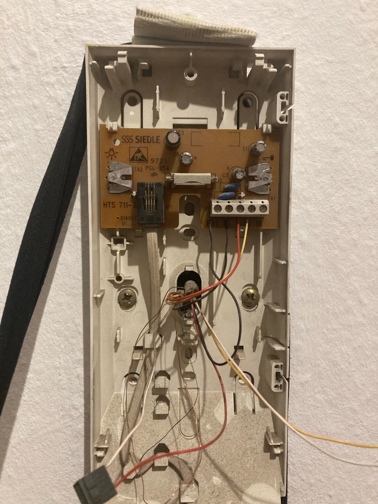
The intercom/buzzer/door-phone in my flat is a Siedle HTS 711-011.
Manuals for other similiar Siedle 1+n systems
| Filename | |
|---|---|
| HTS 811-0 Infosheet (multilang) | HTS_811-0_200035398-00_PI.pdf |
| HTA 711-01 Manual (english) | hta_71101.pdf |
| HTA 711-01 Infosheet (multilang) | hta_71101-1.pdf |
| ZTMO 711 Secondary signal unit | ZTMO_711-0_16_032971_PI.pdf |
| ZT-711 Table-top mount (wiring) | ZT_711-0_4_015143_PI.pdf |
| ZT-711 more wiring diagrams | ZT_711-01_16_032963_PI--.pdf |
| HTC-711 Ciruit board manual | HTC_711-0_115317_PI.pdf |
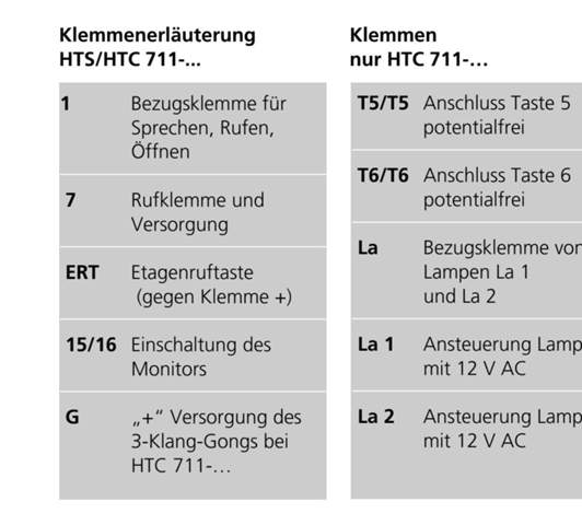
Terminals
As per the datasheet and wiring digarams from Siedle2 (on pages 3-6), the pinout is:
| Pin | Function | Notes |
|---|---|---|
ERT | Etagenruf | Doorbell at apartment door. |
7 | Ca to 1. | |
1 | ||
15 | Klingen | Only works when headset is on (hall sensor). |
16 | Not connected. |
In den Plänen liegt die gemeinsame Ader an Klemme 1 und die Rufader "n" an Klemme 7. Beide Adern müssen im gleichen Kabel geführt werden. Klemme 7 wird im Ruhezustand über das Tasten-Modul mit Gleichspannung versorgt. Solange die Klingeltaste gedrückt wird, steigt die Spannung auf den vollen Wert an.
In the plans, the common wire is connected to terminal 1 and the call wire "n" to terminal 7. Both wires must be routed to the same cable. Terminal 7 is supplied with DC voltage voltage via the button module in the idle state. As long as the button is pressed, the voltage increases to full potential.
When the doorbell outside the apartment door is pressed, ERT is pulled down
Triggering the buzzer
Started on the easy part first, triggering the buzzer for the staircase door. Since the buzzer for the house door is triggered by a simple switch, all we need is a relay that we can control remotely.
Used a Fibaro FGBS-222 implant that I had on hand, which is (among other things) a relay (connected to Z-Wave JS, controlled with Home Assistant).
This is a really simple switch, it just closes a circuit which triggers the buzzer. I soldered wires to each end of the open side of the circuit that the button closes, and use one of the relay contacts on the FGBS-222 to close it.
Instead of using Z-Wave for this part, the FGB-222 will be replaced with a relay connected to an ESP32 with ESPHome that would both detect the doorbell signal and trigger the buzzer.
Home Assistant templating
Configuration for Home Assistant can be found at infra:roles/hass-core/files/packages/doorbell.yaml:
---

script:
  momentary_switch:
    icon: mdi:button-pointer
    mode: parallel
    sequence:
      - service: switch.toggle
        target:
          entity_id: |
            {{ target_switch }}
      - delay:
          milliseconds: |
            {{ press_for_ms | int }}
      - service: switch.toggle
        target:
          entity_id: |
           {{ target_switch }}
    fields:
      target_switch:
        description: |
          entity_id of the switch to toggle like
          a button (a list of entity_id's also works)
        example: switch.smart_implant_out1
      press_for_ms:
        description: |
          how long to press the button, in
          milliseconds
        default: 200

template:
  - binary_sensor:
      - name: doorbell_buzzer
        state: |
          {{ is_state("switch.doorbell_buzzer", "on") }}
        icon: |
          {% if is_state("switch.doorbell_buzzer", "on") %}
          mdi:electric-switch-closed
          {% else %}
          mdi:electric-switch
          {% endif %}

  - button:
      name: doorbell_buzzer
      icon: |
        {% if is_state("switch.doorbell_buzzer", "on") %}
        mdi:electric-switch-closed
        {% else %}
        mdi:electric-switch
        {% endif %}
      press:
        - service: script.momentary_switch
          data:
            target_switch: switch.doorbell_buzzer
            press_for_ms: 200
This assumes that the switch entity on the FGBS-222 module is named
switch.doorbell_buzzer, and creates a button.doorbell_buzzer entity that
triggers the relay.
ESPHome config
Create an internal GPIO switch component
for the internal solid state relay RY1 on GPIO5 for the ESPBell-LITE, and
configure it as a momentary switch:
switch:
  - platform: gpio
    id: "solid_state_relay"
    name: "Doorbell buzzer"
    icon: "mdi:home-lock"
    internal: true
    pin:
      # RY1 on ESPBell-LITE is GPIO5
      number: GPIO5
    restore_mode: "ALWAYS_OFF"
    on_turn_on:
      - delay: "${buzz_time}"
      - switch.turn_off: solid_state_relay
    on_turn_off:
      - lambda: |-
          id(event_buzzer).trigger("buzzed_in");
The create a lock entity with the template platform
that will also reflect the current state of the relay, and add
an event entity with the template platform:
lock:
  - platform: template
    id: lock_buzzer
    name: "Door"
    lambda: |-
      if (id(solid_state_relay).state) {
        return LOCK_STATE_UNLOCKED;
      }
      else {
        return LOCK_STATE_LOCKED;
      }
    unlock_action:
      - lambda: |-
          id(solid_state_relay).turn_on();
    lock_action:
      - lambda: |-
          id(solid_state_relay).turn_off();

event:
  - platform: template
    id: "event_buzzer"
    name: "${hostname} Buzzer"
    icon: "mdi:home-lock-open"
    device_class: "button"
    event_types:
      - "buzzed_in"
To create a button entity analogous to the Home Assistant
template example:
button:
  - platform: template
    id: "buzzer"
    name: "Doorbell buzzer"
    icon: "mdi:home-lock"
    on_press:
      - lambda: |-
          id(solid_state_relay).turn_on();
Detecting doorbell
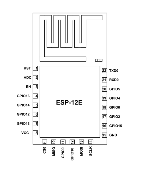
I am currently using a ESPBell-LITE
board for detecting doorbell rings.
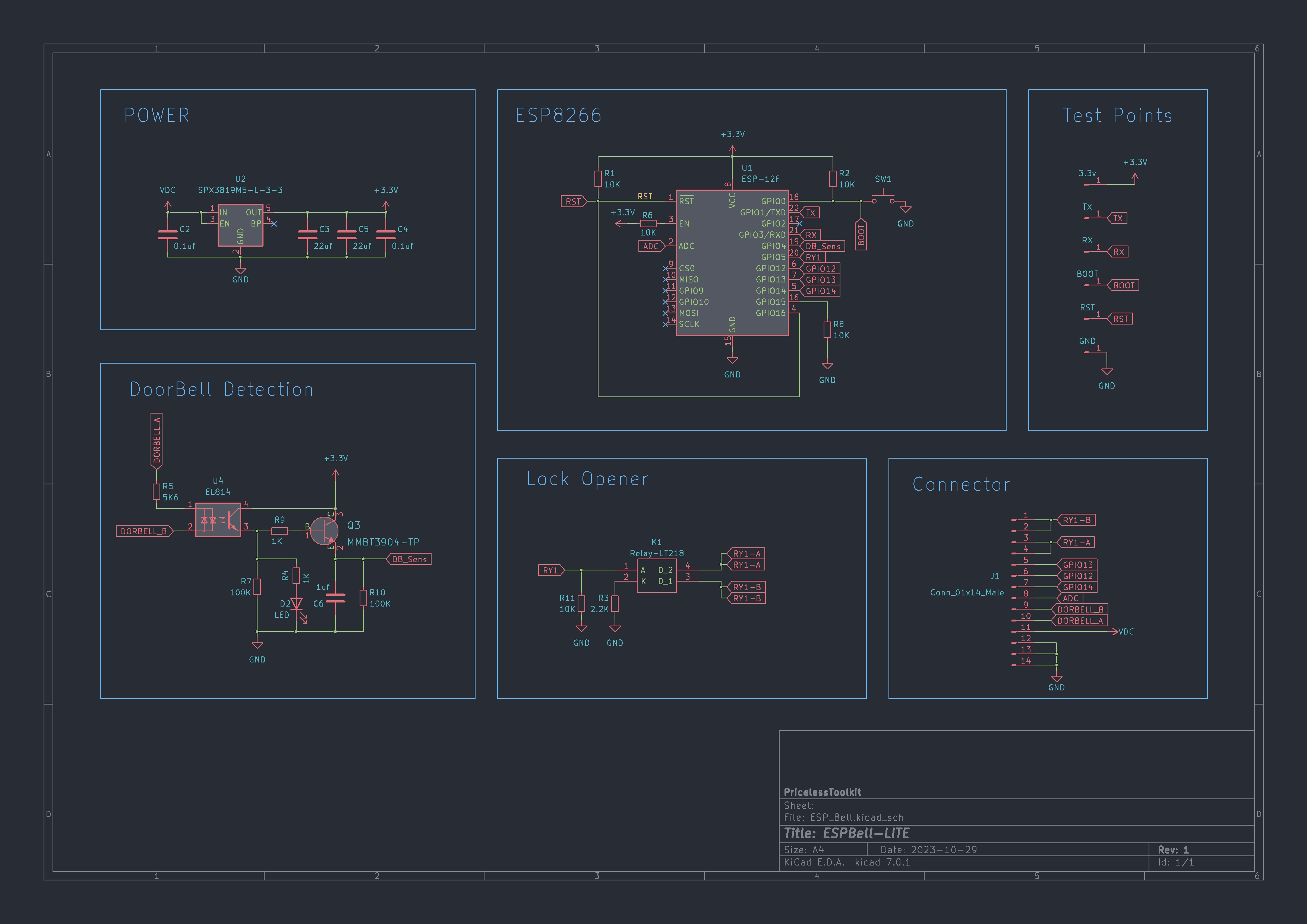
The board has an ESP-12E module, an input optocoupler () for detecting a doorbell signal, and a solid state relay to trigger the buzzer3.
Etagenruf / Doorbell in hallway
The ERT terminal on the Siedle HTS-711 circuit board is
to the terminal 1 while idle and gets pulled up to around
when the doorbell for the flat door is pressed (and approx
to the terminal 7).
ESPHome config
Using a binary_sensor component
for the doorbell (input optocoupler on ESPBell-LITE or with relay connected to
a GPIO pin):
binary_sensor:
  - platform: gpio
    id: "doorbell"
    name: "Doorbell"
    icon: "mdi:bell"
    pin:
      # DB_Sens on ESPBell-LITE is GPIO4
      number: GPIO4
      inverted: false
    filters:
      - delayed_on: 100ms
    on_press:
      - lambda: |-
          id(event_doorbell).trigger("doorbell");
Using for example a SRD-05VDC-SL-C relay, that handles and and wiring it as:
| Relay terminal | |
|---|---|
DC+ | Doorbell 7 |
DC- | Doorbell 1 |
IN | Doorbell ERT |
NO | ESP32 GPIO |
COM | ESP32 GND |
Then when the doorbell button (outside flat) is pressed, the relay is
triggered and the GPIO pin on the ESP is pullen down when the NO
contact is closed.
Enable inverted in the pin config, since the pin gets pulled to when
the NO contact on the relay closes the circuit. Likewise, enable the internal
pull-up (because the relay will pull the pin down) resistor to prevent the
pin from floating.
Add an event entity with the template platform
that can be used in automations in Home Assistant:
event:
  - platform: template
    id: "event_doorbell"
    name: "Doorbell"
    icon: "mdi:bell"
    device_class: doorbell
    event_types:
      - "doorbell"
Hauptklingen / Doorbell outside main entrance
The 15 terminal is pulled up to around when the doorbell
for the flat outside the main entrance is pressed.
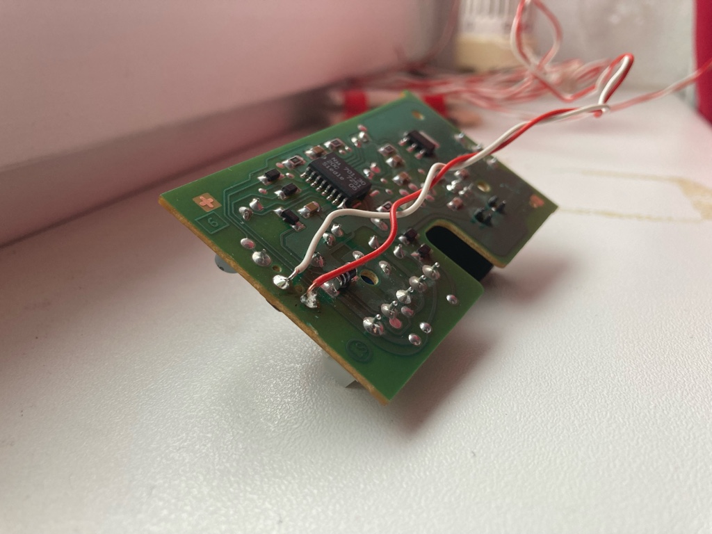
This only works while the headset is in place! There is hall sensor
on the Siedle HTS-711 circuit board, and a magnet in the headset. This
is normally used to mute the ringer when the headset is off, so that
means that it's only possible to use the 15 terminal to detect the
doorbell while the headset is on and the regular shrill ringtone gets
activated.
CHANGELOG
| Date | Comment |
|---|---|
| 2023-03-08 | Connected the buzzer to Fibaro FGBS-222 and HA |
| 2023-09-08 | Added example YAML config for HA |
| 2024-01-30 | Added PDF for FGBS-222 manual |
| 2024-08-04 | Limited pinout |
| 2024-08-07 | Detecting doorbell signal for apartment door |
| 2024-10-18 | ESPBell-LITE config |
References
PricelessToolkit/ESPBell-LITE: ESPHome doorbell module (can handle 1+n)
Intercom Handset Finder Tool. Referenced by ESPBell-LITE as a resource to identify your doorbell.
Mat931/esp32-doorbell-bus-interface:
a PCB design with Gerber files, integrate 2-wiredoorbell intercom.
Integration of my Doorbell in Home Assistant - Syralists blog: Deals with apartment unit doorbells connected in parallel to a bus and reading directly addressed messages.
ESPHome DC sensor components: INA219 (current), INA260 (current and power).
SSS Siedle HTA 811 - Door Phone - Home Assistant forum, similar project but uses the DC-powered HTA series from Siedle.
Reply from Fallingaway24 to "How to smartify my intercom?" - Home Assistant forum, gives a good high-level overview of the general approach.