ESP32 S2 mini
Board summary
| Manufacturer | Wemos |
|---|---|
| Board docs | S2 mini |
| Espressif docs | ESP32-S2 ESP-IDF Programming Guide |
| Datasheet | esp32-s2_datasheet_en.pdf1 |
| Dimensions | esp32_s2_mini_v1.0.0_dimensions.pdf |
| Schematic | esp32_s2_mini_v1.0.0_schematic.pdf |
| Pinout | ESP32_S2_mini_pinout.jpg |
| Pinout (simple) | s2_mini_v1.0.0_4_16x9.jpg |
| PlatformIO | WEMOS LOLIN S2 Mini |
| ESPHome platform | ESP32 Platform2 |
| Recommended framework | esp-idf3 |
| Board ID | lolin_s2_mini4 |
| ESPHome config | packages/boards/esp32s2mini.yaml5 |
arduino-esp32 pins | pins_arduino.h |
| Voltage regultor | ME6211C33 |
Specifications
| Name | |
|---|---|
| Chipset | ESP32-S2FN4R2 |
| Wi-Fi | 2.4 GHz b/g/n |
| Bluetooth | None |
| Processor | 32-bit LX7 single-core |
| Clock speed | |
| SRAM | 320 KB |
| PSRAM | 2 MB (for ESP32-S2FN4R2) |
| Flash | 4 MB |
| Operating voltage | 6 |
| Max input voltage | 7 |
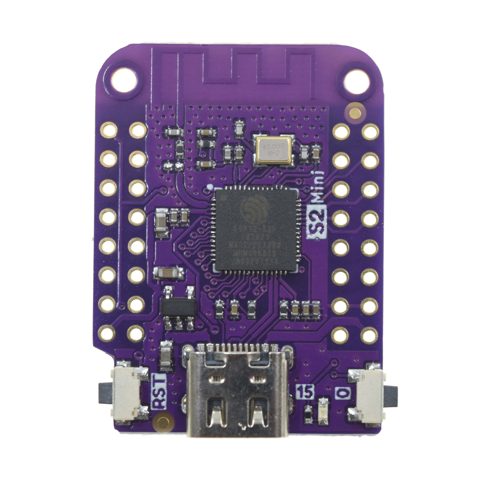
I have some boards that say ESP32-S2FH4 on the chip (which should have 4 MB
flash, and no PSRAM), though the official Wemos docs6 says they
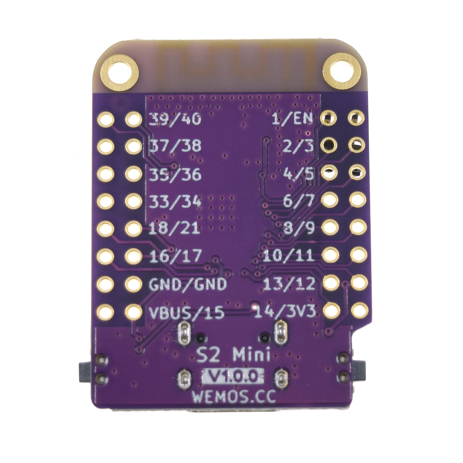
should have ESP32-S2FN4R2. The silkscreen prints match and have v1.0.0 on
the backside (but without the white background). There are some reports from others
that have also gotten supposed Wemos ESP32 S2 Mini boards with S2FH4 instead
of S2FN4R2 -- so these might actually be counterfeits.
ESPHome support
Board config:
esp32:
  board: lolin_s2_mini
  variant: ESP32S2
  framework:
    type: esp-idf
Config for status_led (on GPIO15):
light:
  - platform: status_led
    name: "Status LED"
    id: esp_status_led
    icon: "mdi:alarm-light"
    restore_mode: ALWAYS_OFF
    pin:
      number: GPIO15
      inverted: false
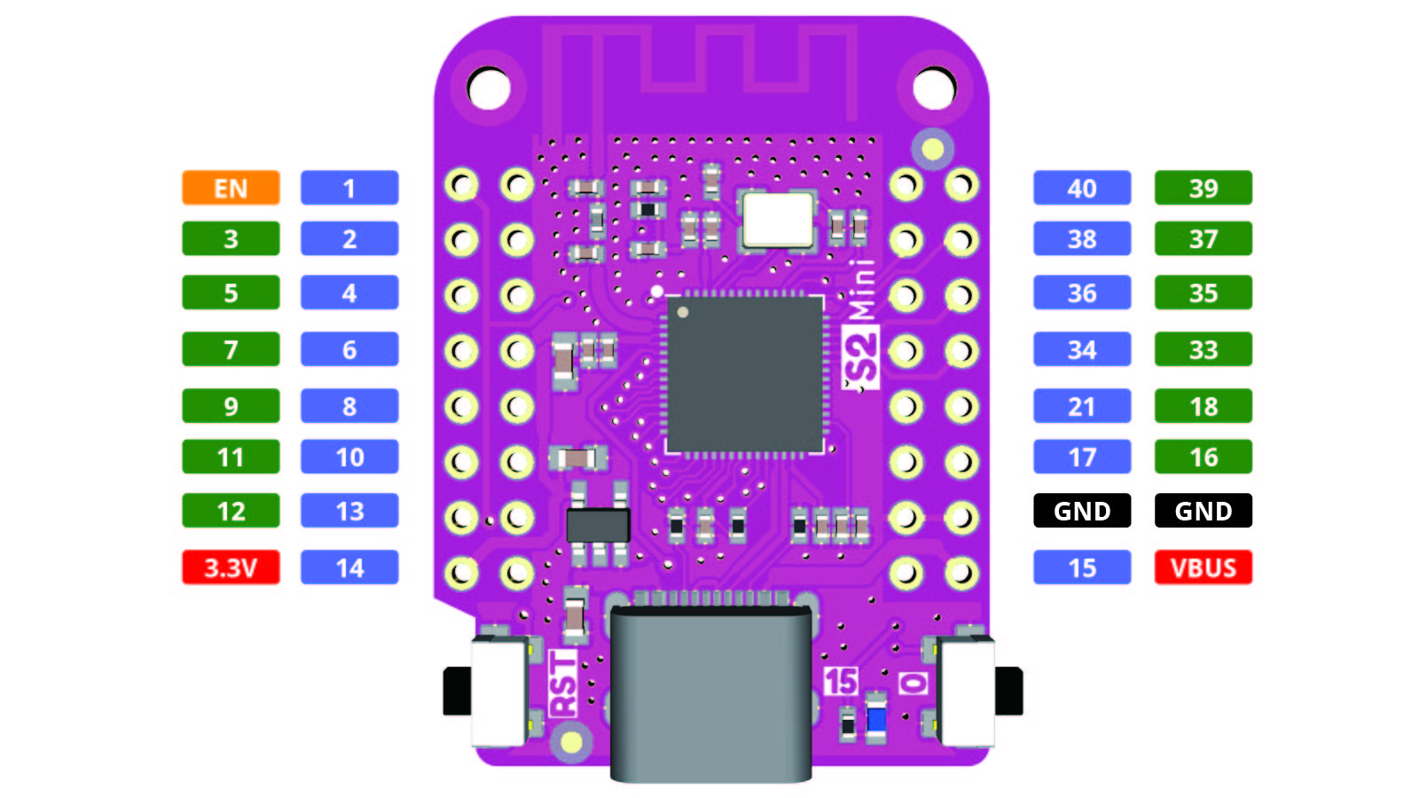
Pinout
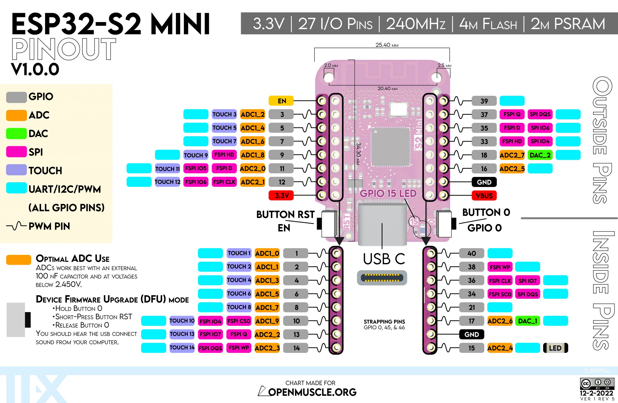
Interfaces
The ESP32 S2 Mini board has 2x I²C buses, 4x SPI, 8x PWM channels, 2x ADCs, 2x 8-bit DAC, 2x UART channels, 1x I²S bus and an USB OTG interface8.
| Interface | Pins | Notes |
|---|---|---|
| ADC1 | GPIO1-GPIO10 | |
| ADC2 | GPIO11-GPIO14, GPIO19-GPIO20, DAC_1, DAC_2 | Not usable when Wi-Fi is enabled9. |
| UART | Any GPIO pins | |
| LED PWM | Any GPIO pins (maybe not GPIO15) | |
| I²C | Any GPIO pins | Schematic10 shows SDA on GPIO33 and SCL on GPIO35 (see below) |
| SPI | GPIO9-GPIO14 and GPIO33-GPIO37 | 4x SPI interfaces (SPI0-SPI3) |
| DAC | DAC_1: GPIO17, DAC_2: GPIO18 | 2x DAC interfaces |
| I²S | Any GPIO pins (LRCLK, BCLK, MCLK) |
Unsafe pins (strapping pins, trigger bootloader modes if pulled up/down):
GPIO0(Button 0): SPI boot mode, pull-up.GPIO45: VDD_SPI voltage, defaults as pull-down .GPIO46: SPI boot mode, pull-down.
Other notes about pins
GPIO33: I²C SCL (schematic)GPIO35: I²C SDA (schematic)GPIO17:DAC_1GPIO18:DAC_2GPIO11-GPIO20(ADC2): Not usable when Wi-Fi is enabled9.VBUS: isVINor , directly connected to on the USB-C connector. Max input voltage is 7.- Power supply for
GPIO33,GPIO34,GPIO35,GPIO36andGPIO37is configurable to be either VDD3P3_CPU (default) or VDD_SPI. GPIO10,GPIO34:FSPI/SPI CS0(Chip select).GPIO12,GPIO36:FSPI/SPI CLK(Clock).- Supports LEDC PWM from esp-idf11.
- The ESPHome
ledccomponent only supports usingGPIO0-GPIO3312. - For pin mappings used by the
arduinoframework13, seepins_arduino.h.
Notes on I²C on the S2 Mini
Generally I²C components seem to work better using the arduino
framework, especially when using pins other than GPIO33 and GPIO35.
If you are trying to get some I²C component to work, and you are
using esp-idf but it's not working as expected, you should try switching
to arduino before spending too much time debugging on esp-idf.

According to the datasheet any GPIO pins can be used for the I²C bus. But then the schematic shows:
GPIO33:SDAGPIO35:SCL
It seems that the datasheet is "more correct", and that it is in fact possible
to use any GPIO pins for I²C (though GPIO33 and GPIO35 might be handling
I²C on the hardware level, other pins might be using them on the software
level?).
Using I²C with the esp-idf framework, you might see errors like:
[C][i2c.idf:061]: I2C Bus:
[C][i2c.idf:062]:   SDA Pin: GPIO16
[C][i2c.idf:063]:   SCL Pin: GPIO18
[C][i2c.idf:064]:   Frequency: 50000 Hz
[C][i2c.idf:073]:   Recovery: failed, SDA is held low on the bus
The i2c component in esp-idf has two undocumented14 parameters,
sda_pullup_enabled and scl_pullup_enabled, that can be used to enable or
disable the internal pullout resistors. By default, they are enabled
on GPIO33 and GPIO35, and according to the datasheet from Espressif, the S2
Mini has both internal pull-up and pull-down resistors on all GPIO pins.
To use pins other than GPIO33 and GPIO35, you need to disable or enable these internal
pull-up resistors. Weather you need to enable or disable them seem to depend on what device
you are connecting. For an PN532 RFID/NFC reader, you need to disable them:
i2c:
  sda_pullup_enabled: false
  scl_pullup_enabled: false
Then you can configure any GPIO pins for I²C:
i2c:
  - id: i2c_bus0
    sda: GPIO33
    scl: GPIO35
    sda_pullup_enabled: false
    scl_pullup_enabled: false
This only works on the esp-idf framework. Using the arduino framework,
these options are not available, and I²C seems to work better with it in
general.
There are some reports
of the arduino framework working better for I²C. This seems to be true, as I
have only managed to get SSD1306 OLED displays working using the arduino
framework so far.
Found someone on reddit saying that the S2 Mini doesn't have internal pull-up
resistors
on GPIO33 and GPIO35. But i don't think that is true since disabling them
(by setting sda_pullup_enabled and scl_pullup_enabled on esp-idf) is what
got a PN532 to start working.
This also works well with YAML anchors and the ESPHome !include syntax if you
use packages. You can specify defaults for the i2c components, and then using
the above you can override them in the file importing it.
I'm unsure why datasheet says that any pins can be used for I²C when the
schematic shows GPIO33 and GPIO35 being wired as SDA and SCL, maybe
it's done in software or software/firmware can bridge other GPIO pins to the
internal system pins for I²C on the chip.
Side-note: Sometimes, for some components, it can help to set the frequency to for the I²C bus.
Enter bootloader mode to program over USB
To put the ESP32 S2 Mini into bootloader mode:
- Unplug USB/power
- Hold both buttons (Marked
RSTand0) - Plug in USB
- Release
RST("reset") - Release
0("boot")
This puts the device into boot loader mode where it can be flashed. On Linux it
appears as /dev/ttyACM0 (or higher number if 0 already exists). On Mac OS
it shows up as /dev/tty.usbmodem01 and /dev/cu.usbmodem01.
On systems with AppArmor, it gets in the way and disrupts the access ("protocol error")
Useful tool: Adafruit ESPTool only works on Chrome. Can be used to erase memory.
Erase memory with esptool.py:
$ esptool.py --port COM13 erase_flash
Flashing my bootstrap config on Mac OS, with esph.py:
$ esph.py run esp32-s2-mini --name study-VINDRUTA --user --domain s21.sudo.is --device /dev/tty.usbmodem01
Or using esphome directly:
$ esphome -s node_name $namee -s lower_node_name $hostname -s domain $domain run esp32-s2-mini.yaml --device /dev/tty.usbmodem0
Some incomplete answers online that I stitched this together from:
press both buttons and release programming button, s2 mini set for programming15
hold 0, press reset, release 016
Be careful to not accidentally break one of the buttons off the board.
References
esphome/feature-requests#996 - GitHub: ESPHome support for board requested