NodeMCU ESP8266
Board summary
| Manufacturer | Various, ESP8266 is made by Espressif Systems |
|---|---|
| Datasheet | ESP8266-NodeMCU-Datasheet.pdf1 |
| Pinout | nodemcu_esp8266_pinout.jpg |
| Arduino pins | nodemcu/pins_arduino.h |
| ESPHome device | NodeMCU ESP8266 |
| ESPHome platform | ESP8266 Platform |
| ESPHome config | packages/boards/esp8266nodemcu.yaml2 |
| Framework | arduino3 |
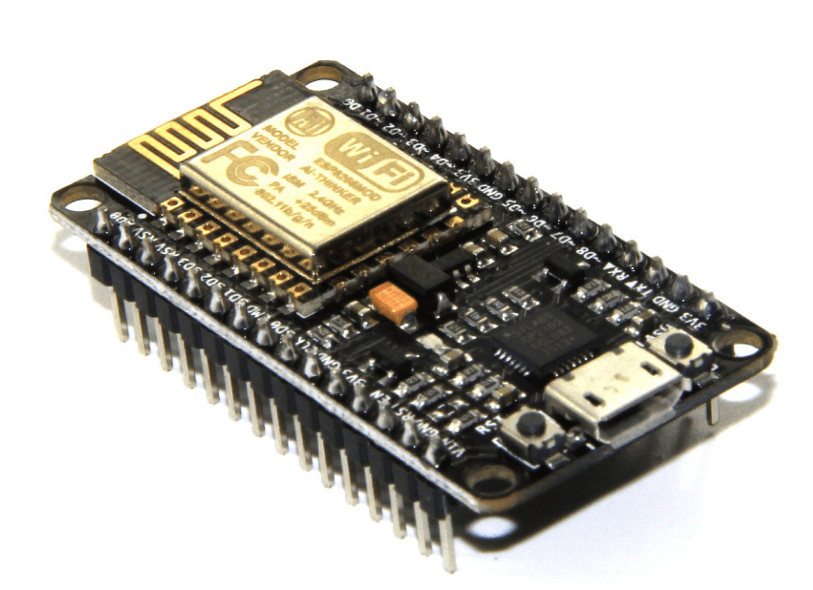
NodeMCU ESP8266 board with micro-USB connector (USB-C variants are also available)
ESPHome support
Board config:
esp8266:
  board: nodemcuv2
Config for status_led (on some boards):
light:

  # This is the built-in blue status LED
  - platform: status_led
    name: "Status LED"
    id: esp_status_led
    icon: "mdi:alarm-light"
    entity_category: "config"
    restore_mode: ALWAYS_OFF
    pin:
      number: D4
      inverted: true

  # Only present on some boards, this is the built in AUX led, next to the UART chip
  - platform: status_led
    name: "AUX LED"
    id: esp_aux_led
    icon: "mdi:alarm-light"
    entity_category: "config"
    restore_mode: ALWAYS_OFF
    pin:
      number: D0
      inverted: true
Pinout
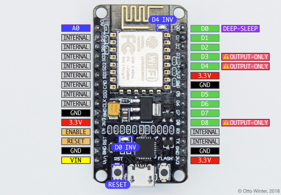
Pins
The NodeMCU pin numbering on the silkscreen (e.g. D0, A0) is different from the internal
pin numbering. ESPHome knows how to map the silkscreen pins numbers to internal pin numbers4.
| Silkscreen pin | Internal pin | Interface | Notes |
|---|---|---|---|
A0 | GPIO17 | ADC | |
D0 | GPIO16 | Deep-sleep wakeup, AUX LED (inverted) | Can be accessed from RTC, weak pull-down |
D1 | GPIO5 | I²C SCL | High impedance |
D2 | GPIO4 | I²C SDA | High impedance |
D3 | GPIO0 | Controls boot mode (strapping pin), weak pull-up | |
D4 | GPIO2 | Blue LED (inverted) | Controls boot mode (strapping pin), weak pull-up |
D5 | GPIO14 | SPI CLK/SCK | Weak pull-up |
D6 | GPIO12 | SPI MISO | Weak pull-up |
D7 | GPIO13 | SPI MOSI | Weak pull-up |
D8 | GPIO15 | SPI CS/SS | Controls boot mode (strapping pin), weak-pull-up |
RX / D9 | GPIO3 | UART Serial RX | |
TX / D10 | GPIO1 | UART Serial TX |
The ESP8266 can only use the designed pins for each interface (SPI, UART, I²C, etc), other pins can't be used for them.
| Interface | Pins |
|---|---|
status_led | D4 / GPIO2 |
UART RX | RX / D9 / GPIO03 |
UART TX | TX / D10 / GPIO01 |
SPI MISO | D6 / GPIO12 |
SPI MOSI | D7 /GPIO13 |
SPI CLK/SCK | D5/ GPIO14 |
SPI CS/SS | D8 / GPIO15 |
| ADC | A0 / GPIO17 |
I²C SCL | D1 / GPIO5 |
I²C SDA | D2 / GPIO4 |
Some notes about pins on NodeMCU ESP82663:
- The internal pull-up/-down resistors have values of to 5.
- In some cases pins marked as
INTERNALon the pinout can be used. D0can be used to wake the device up from deep sleep if the pin is connected to theRESETpin.D3,D4,D8: Strapping pins that control boot mode. If these are used as general purpose GPIO pins they should be in the default states to boot from flash:D3(GPIO0):HIGHD4(GPIO2):HIGH(blue status led)D8(GPIO15):LOW
D4(GPIO2): connected to bluestatus_led, in inverted mode.D0(GPIO16, only on some boards): AUX LED next to the UART chip, in inverted mode.A0(GPIO17): ADC pin, measures voltages from to . Can be used as a normal GPIO pin.VIN: Voltage input, board can be powered by external power supply on this pin. Some boards support up to , other .ENABLE/RESET: Board resets when these pins are triggered. Difference is how they handle voltages above .
When the ESP8266 boots, the three strapping pins are checked to determine which boot mode to enter3:
| Mode | UART code | GPIO0 (D3) | GPIO2 (D4) | GPIO15 (D8) |
|---|---|---|---|---|
| Boot from flash (normal) | 3 | HIGH | HIGH | LOW |
| Program from UART | 1 | LOW | HIGH | LOW |
| Boot from SD-card | 4-7 | Any | Any | HIGH |
The reset causes are documented in the datasheet and are as follows:
| UART code | Reset cause |
|---|---|
0 | Undefined |
1 | Power on reboot |
2 | Deep-sleep wake-up or external reset |
4 | Hardware WDT reset |
On boot, the first line in the UART output tells you which boot mode was used and the reset cause:
rst cause:4, boot mode:(3,6)
Here the reset cause was 4 and the boot mode was 3.
References
Components 101 NodeMCU ESP8266