UHER Akustomat F411
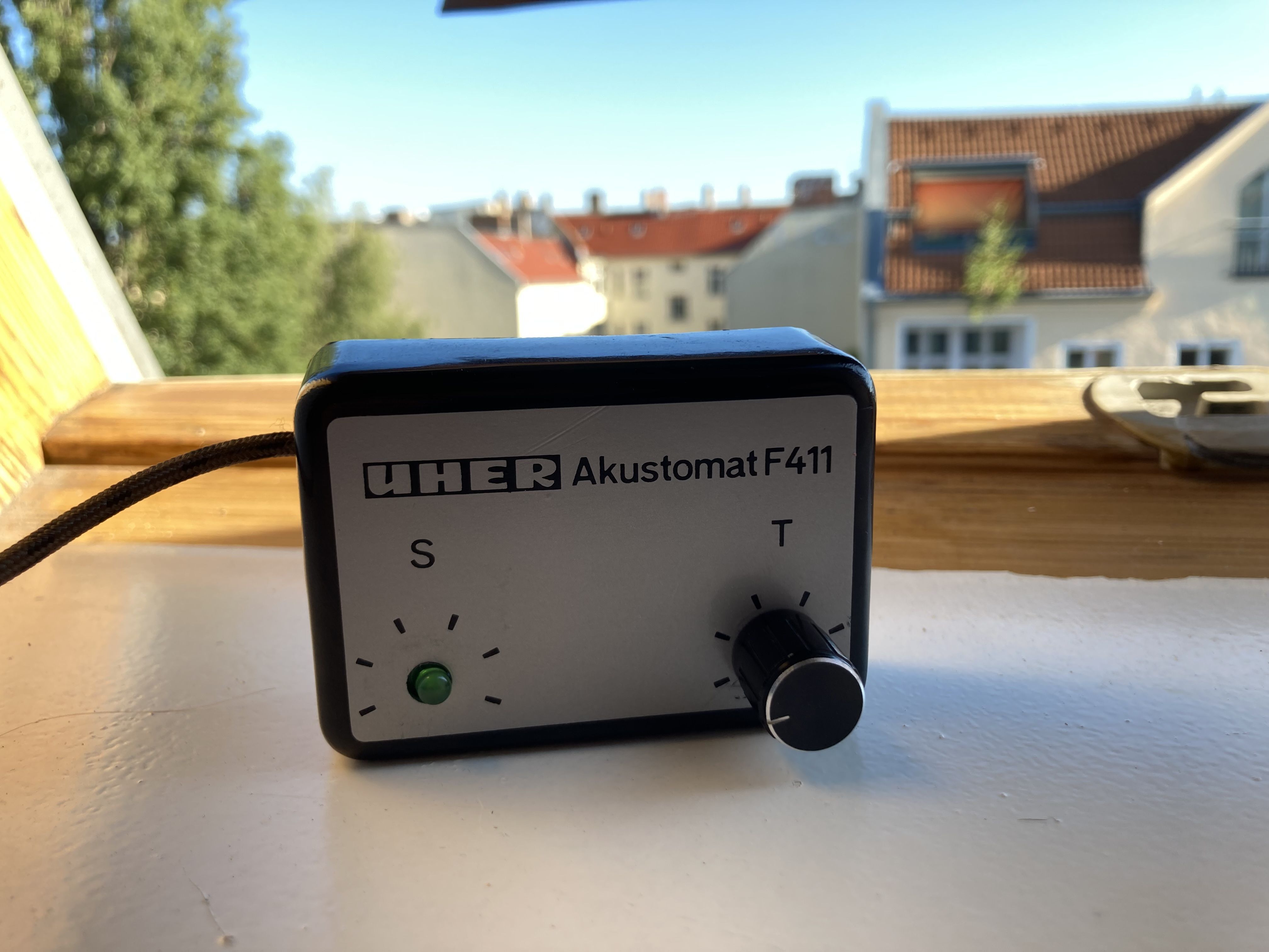
UHER Akustomat F411 - first iteration
Overview
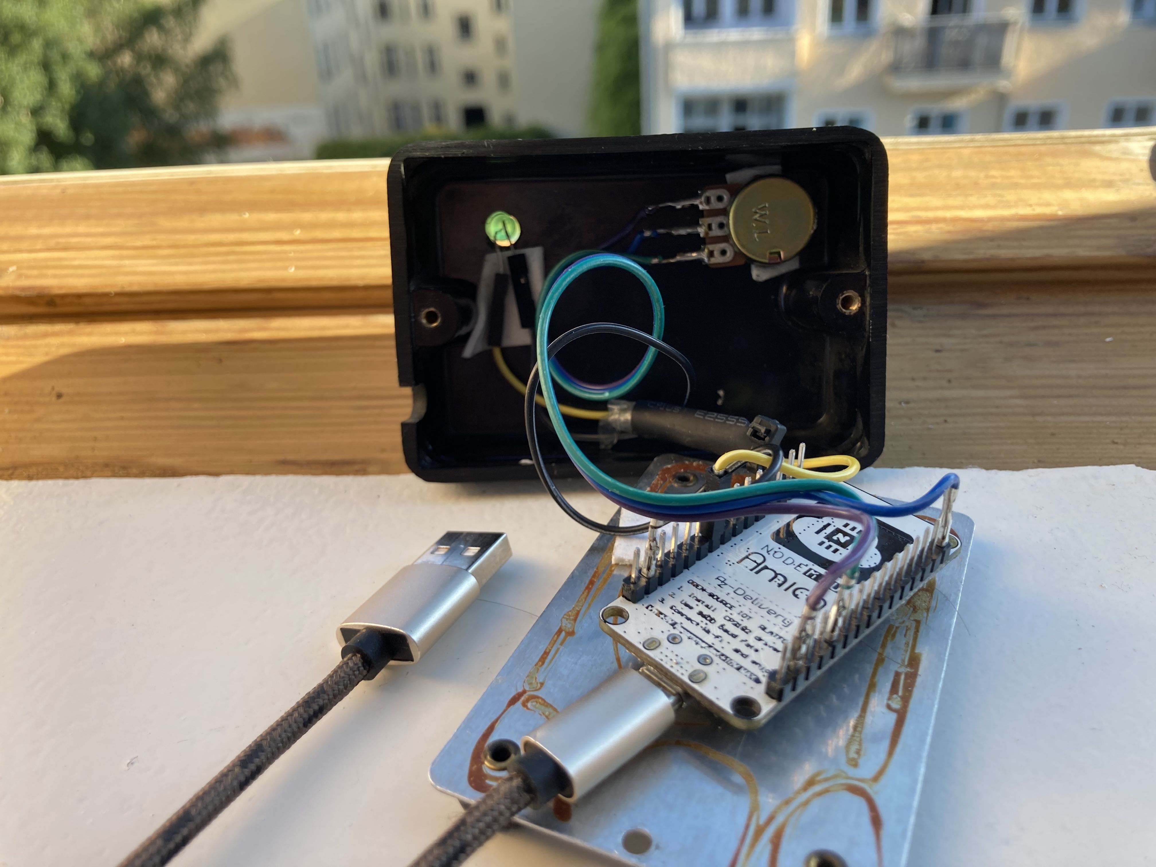
This is an old UHER Akustomat F4111, that has been stripped of it's original internals2 and replaced with:
- ESP32 C3 SuperMini
- Potentiometer for volume control, using ADC3 on the ESP32.
- Button with an LED4, brightness of the LED is set with PWM5 according to the volume level.
I use this device to give physical control to an OwnTone output. The current iteration uses an ESP32 C3 SuperMini running ESPHome.
Iterations
This (simple) project has gone through multiple iterations and improvements:
-
ESP8266 NodeMCU with a potentiometer, later added a single LED diode
This was limited by the ESP8266 only having a single ADC, and lacks hardware PWM for LEDs. The ESP8266 I was using was also a dev board with pre-soldered pins that made it more bulky that it needed to be.
-
ESP32 S2 Mini with a potentiometer and LED button.
The internal wiring was still a mess, but switching to an ESP32 added hardware PWM for the LED with ESP32 LEDC output5.
-
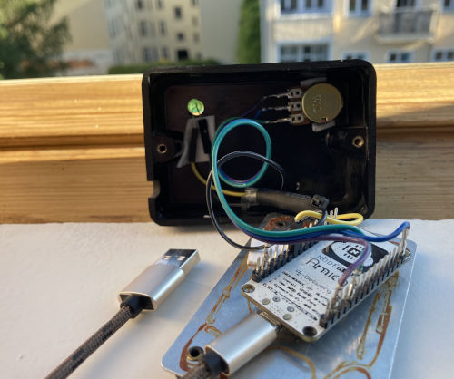
ESP32 C3 SuperMini (current iteratation) with potentiometer and LED button where the brightness of the LED follows the volume level.
The wiring on this iteration is pretty clean. The biggest hurdle to that was that ESP32 C3 SuperMini only has one GND pin, and this project currently has 3x GND connections. Was able to structure two wireboards (that has inter-connected pin holes) and use 2.54mm JST connectors to make a relatively clean design.
The next iteration should be a custom designed PCB that eliminates the need for internal wiring completely.
Components
Potentiometer
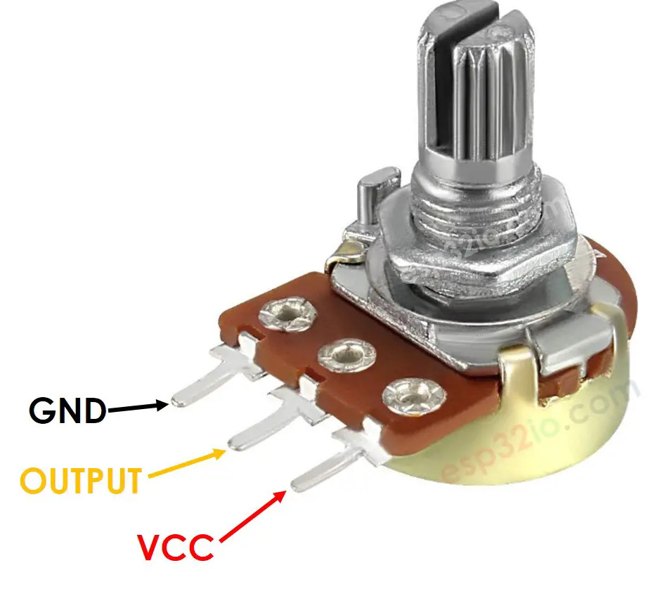
Potentiometer pinout
LED Button
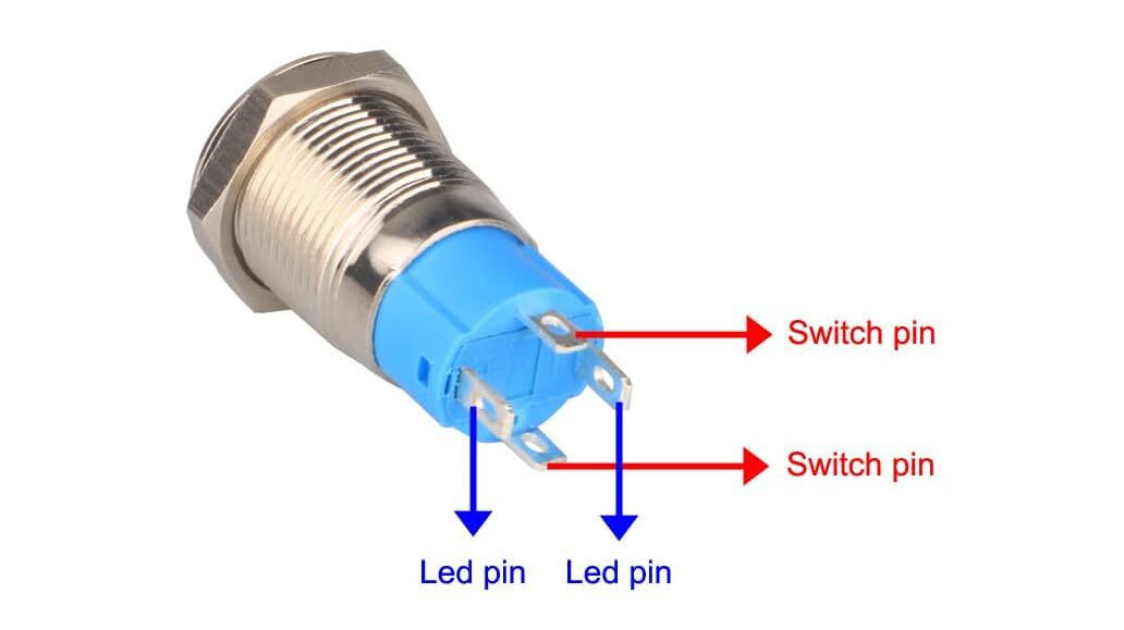
LED button pinout
Pull-up and pull-down resistors
Either connect the the switch pins from a GPIO to GND with the internal
pull-up resistor enabled or from from a GPIO to 3V3 with internal pull-down
resistor enabled.
It is preferable to connect the switch between a GPIO and GND using pull-up
resistors so that you don't have wires running away from the board where
they could short to ground by accident and fry something.
binary_sensor:
  - platform: gpio
    id: gpio_button_s
    name: "UHER Akustomat F411 S"
    pin:
      number: "${binary_sensor_gpio}"
      inverted: true
      mode:
        input: true
        pullup: true
        pulldown: false
    publish_initial_state: true
When the button is pressed, the circuit is pulled LOW so we need to configure
the pin with inverted enabled.
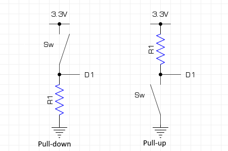
A pull-up resistor sits between GPIO and /3V3 and "pulls up to
positive", while a pull-down resistor sits between GPIO and GND and "pulls
down to negative" instead. The internal pull-up/pull-down resistors on the
ESP32 does this internally on the board.
References
Home Assistant forum comment by tom_l on using pull-up/pull-down resistor for switch on GPIO, illustrated with a simple schematic.