ESP32 C3 Super Mini
Board summary
| Manufacturer | Maker go |
|---|---|
| Board docs (C3 mini) | C3 Mini |
| Datasheet (C3 series) | esp32_c3_datasheet.pdf1 |
| Datasgeet (C3 Super Mini) | ESP32-C3_SuperMini__datasheet_artronshop.co.th.pdf |
| Technical Reference Manual | esp32-c3_technical_reference_manual_en.pdf |
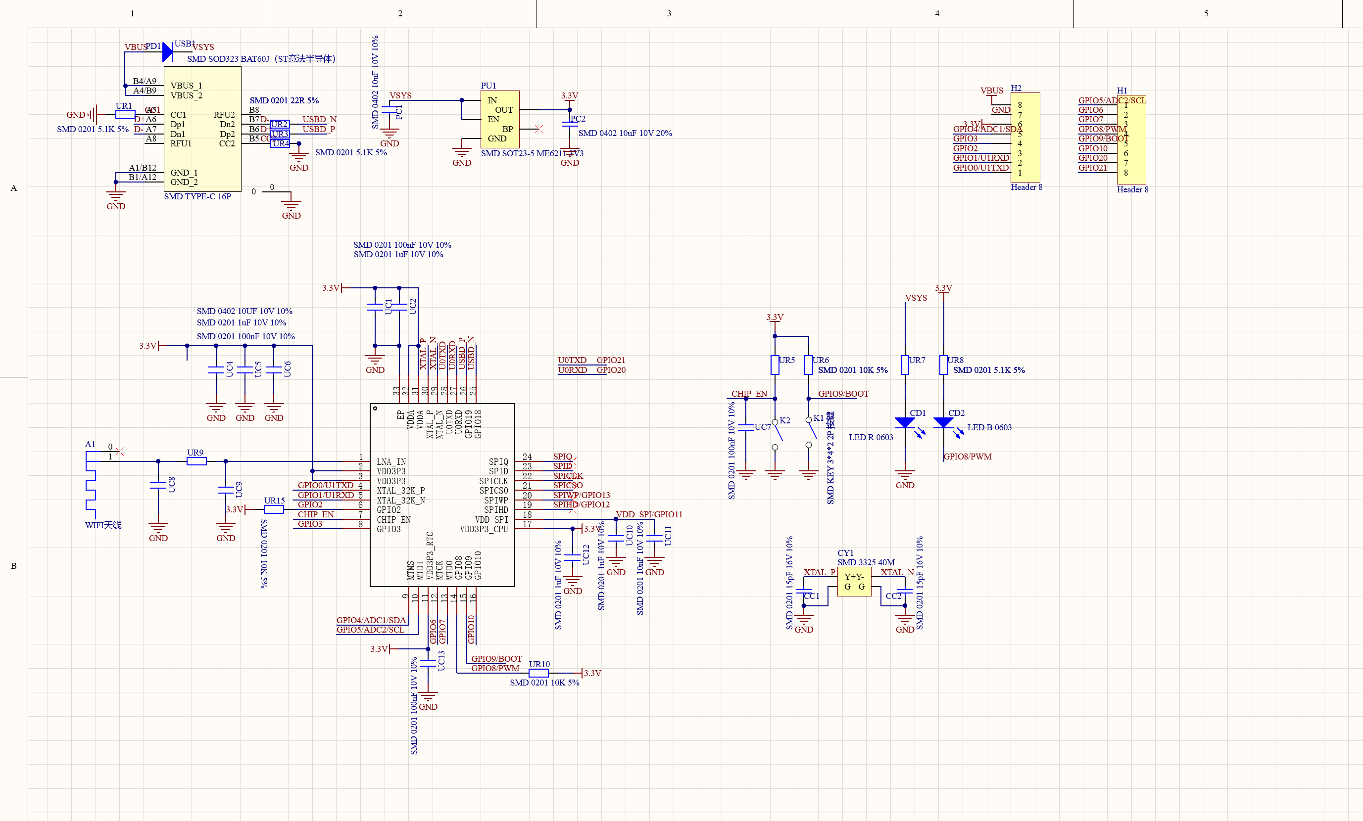
| Schematic | esp32-c3-supermini-schematic.png |
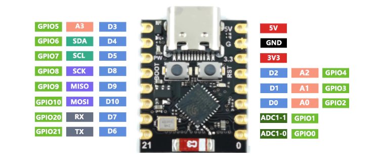
| Pinout | esp32_c3_supermini_pinout.jpg (topside), esp32_c3_supermini_pinout_under.jpg (underside) |
| Microsoft | ESP32-C3 SuperMini |
| PlatformIO | Espressif ESP32-C3-DevKitM-12 |
| Announcement | Introducing ESP32-C3 |
| ESPHome platform | ESP32 Platform3 |
| Recomended framework | esp-idf4 |
| ESPHome config | packages/boards/esp32c3supermini.yaml5 |
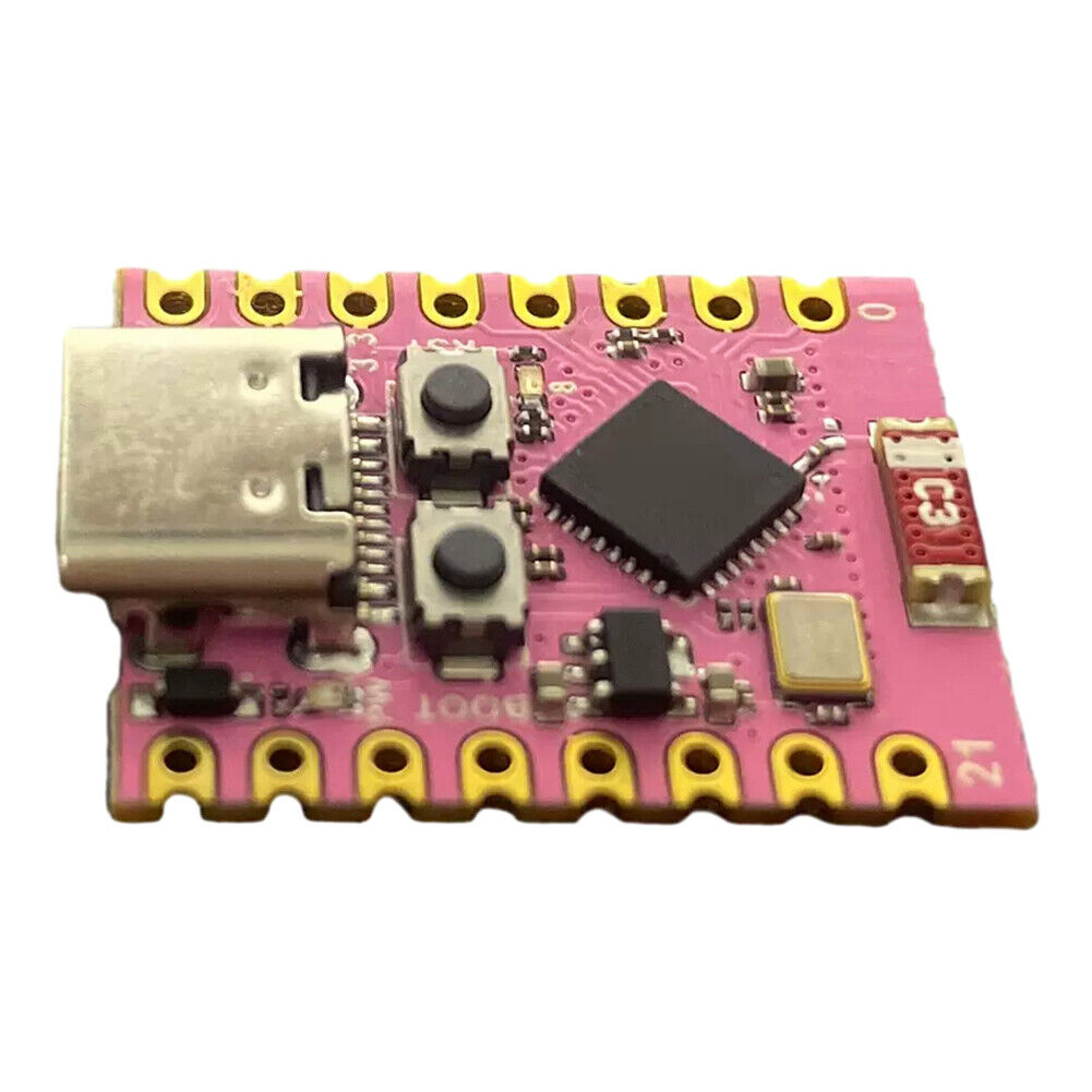
ESP32 C3 Super mini
Specifications
| Name | |
|---|---|
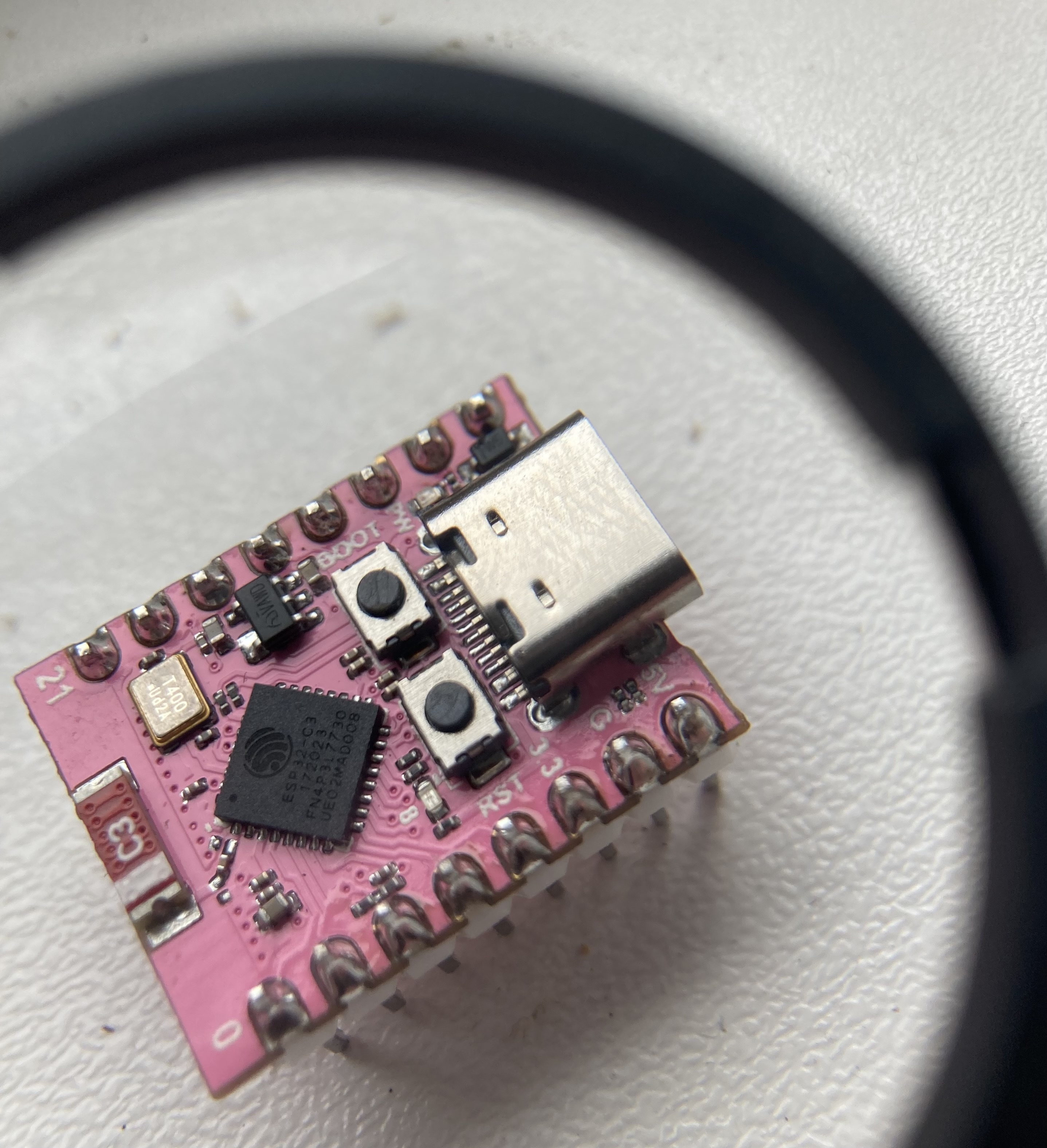
| Chipset | ESP32-C3 FN4 (172023 P3L7730) |
| Wi-Fi | 2.4 GHz b/g/n |
| Bluetooth | BLE 5 |
| Processor | 32-bit RISC-V single-core |
| Clock speed | |
| SRAM | 320 KB |
| PSRAM | N/A |
| Flash | 4 MB |
| Flash frequency | |
| Flash mode | QIO |
| Operating voltage | |
| Supply voltage |
ESPHome support
Board config:
esp32:
  board: esp32-c3-devkitm-1
  variant: ESP32C3
  framework:
    type: esp-idf

esphome:
  platformio_options:
    board_build.flash_mode: dio
Config for status_led (on GPIO8):
light:
  - platform: status_led
    name: "Status LED"
    id: esp_status_led
    icon: "mdi:alarm-light"
    pin:
      number: GPIO8
      inverted: true
    restore_mode: ALWAYS_OFF
Pinout
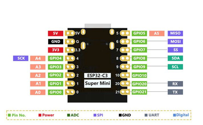
Interfaces
The ESP32 C3 series has 2x ADCs, 6x PWM channels, 2x UART, 1x I²C and 3x SPI6.
| Interface | Pins | Notes |
|---|---|---|
| ADC1 | GPIO0-GPIO4 | |
| ADC2 | GPIO5 | Not usable when Wi-Fi is enabled6. |
| UART | Any GPIO pins | |
| LED PWM | Any GPIO pins | 6x PWM channels |
| I²C | Any GPIO pins | |
| SPI0 | None | Used by internal GDMA controller |
| SPI1 | None | Used by CPU |
| SPI2 | Any |
Pin mappings:
| Silkscreen pin | Internal pin | Notes |
|---|---|---|
0 | GPIO0 | ADC1 |
1 | GPIO1 | ADC1 |
2 | GPIO2 | ADC1, boot mode / strapping pin |
3 | GPIO3 | ADC1 |
4 | GPIO4 | ADC1, JTAG |
5 | GPIO5 | JTAG |
6 | GPIO6 | JTAG |
7 | GPIO7 | JTAG |
8 | GPIO8 | Blue status_led (inverted), boot mode / strapping pin |
9 | GPIO9 | Boot mode / strapping pin, boot button |
10 | GPIO10 | |
20 | GPIO20 | |
21 | GPIO21 |
Some notes on pins:
- The blue
status_ledis onGPIO8and is inverted. - The Wemos C3 Mini documentation shows a RGB led on
GPIO8, but that might be on the C3 Mini only (and not SuperMini). Usingstatus_ledit toggles a blue on-board LED on the C3 Super Mini. - The BOOT button is wired to
GPIO9 - JTAG is available on
GPIO4-GPIO7.
Strapping pins
| GPIO pin | Default | Controls |
|---|---|---|
GPIO2 | Floating | Boot mode |
GPIO8 | Floating | Boot mode, ROM message printing |
GPIO9 | Pull-up | Boot mode |
Boot modes
| Mode | GPIO2 | GPIO8 | GPIO9 |
|---|---|---|---|
| SPI boot (default) | HIGH | Any | HIGH |
| UART/JTAG download | HIGH | HIGH | LOW |
Enter bootloader mode to program over USB
If the ESP C3 SuperMini is unprogrammed, it seems to enter bootloader mode by default when plugged in with USB. If it has been programmed, it will connect and disconnected. To put the ESP32 C3 SuperMini into bootloader mode (if it is connecting/disconnected, or has been programmed):
- Plug in USB
- Hold both buttons
- Release both buttons at the same time
Before you press the buttons it will connect and disconnect.
Watching dmesg while you do this is helpful:
$ sudo dmesg -w

usb 3-2: Product: USB JTAG/serial debug unit
usb 3-2: Manufacturer: Espressif
cdc_acm 3-2:1.0: ttyACM0: USB ACM device

usb 3-2: USB disconnect, device number 89
On Linux (Fedora) it show up as /dev/ttyACM0 (or ttyACM1 etc).
References
ESP32 Forum post "Question about Super Mini ESP32-C3?": clarfies pin restrictions
ESP32-C3 Development Board ESP32 SuperMini - Tindie: names "Maker go" as the manufacturer, and has schematics.