GPIO
GPIO pin as GND and 3v3
You can power sensors and other low-draw components on GPIO pins alone. On the ESP32
the GPIO pins can usually supply up to around or so, but the "real" 3v3 pin
can supply more. It's really just doable for some low-power sensors.
As GND
To configure a pin as GND, you just have to define it as an output pin that has
not been turned on:
output:
  - platform: gpio
    id: fake_gnd
    pin:
      number: ${gpio}
      mode:
        pulldown: true
        output: true
Somewhat confusingly, the pin must be defined as output. Enable pulldown in the
pin config when using it as GND.
As 3v3
There are several ways to configure a GPIO pin as a source. The simplest way is to
configure the pin as inverted:
output:
  - platform: gpio
    id: supply_3v3
    pin:
      number: ${gpio}
      inverted: true
      mode:
        # Optionally set the maximum amount of current (esp-idf only)
        drive_strength: 40mA
        pullup: true
        output: true
Enabaling pullup activates the internal pull-up resistor on ESP32 boards, which
is a resistor from the GPIO to 3v3.
If you are using a strapping pin that changes the boot mode by being pulled
HIGH, and you will need to define a on_shutdown automation that turns the pin
on.
Since the pin is inverted, you'll need to call turn_on() to turn it off.
Note that if the ESP looses power, there is no guarantee that the pin will be in
the correct state on boot. Thus it is safer to configure the pin to be turned on
during or after booting, so that it is programmed to be LOW when the ESP32 boots.
If you configure the output without inverted it will be LOW on boot, needing
an on_boot automation to turn_on and pull it up to HIGH.
output:
  - platform: gpio
    id: supply_3v3
    pin:
      number: ${gpio}
      mode:
        pullup: true
        output: true

esphome:
  on_boot:
    priority: 90
    #  800: hardware init, vital components
    #  600: most sensors are ready
    #  250: wifi is initialized
    #  200: network connections and the esphome tcp api are set up
    #  100: everything is initialized
    then:
      - output.turn_on: supply
Another way is to just use the pin in an gpio switch:
switch:
  - platform: gpio
    id: supply_3v3
    name: "${hostname} GPIO 3v3"
    pin:
      number: ${gpio}
      mode:
        pullup: true
        output: true
Unless internal is enabled, this will show up and work like a regular switch
entity in Home Assistant, so it can be turned on/off at will.
Both of these methods are useful for strapping pins as they avoid setting the state of the pin in flash and do it at runtime instead.
Pull-up and pull-down resistors
A pull-up resistor sits between GPIO and /3V3 and "pulls up to
positive", while a pull-down resistor sits between GPIO and GND and "pulls
down to negative" instead.
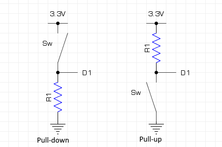
ESP32 has internal pull-up/pull-down resistors that do this internally on the board (but ESP8266 does not have them).
binary_sensor:
  - platform: gpio
    id: binary_sensor_gpio
    name: "Press"
    pin:
      number: "${gpio_pin}"
      inverted: true
      mode:
        input: true
        pullup: true
        pulldown: false
    publish_initial_state: true
Configuring the pin with pulldown will activate this internal resistor on the ESP32
and connect the GPIO pin to the (real) GND with a resistance.
References
Pull-up and Pull-down resistors - EEPower: primer on pull-up/pull-down resistors and how they are used on MCUs.
Powering sensors - Alex Mekkering: Using GPIO pins as 3V3 or GND.
Home Assistant forum comment by tom_l on using pull-up/pull-down resistor for switch on GPIO, illustrated with a simple schematic.