ESPHome boards
Overview
The ESP32 and ESP8266 chips are made by Espressif, and they publish the datahseets online. Different boards (or "dev kits") are made by a variety of manufacturers that source the ESP chips from Espressif.
I have pretty much only been using ESP32/ESP8266 boards with ESPHome so these notes are very ESPHome-centric.
Boards
There are a lot of different chips, boards, devkits and variants there of available1. Almost all of them are cheap, eBay is a is a good source for buying them but expect them to be shipped from China and delivery times reflecting that.
The FCC ID's (often printed on the metal cover) are useful for identifying boards as they are listed in the Wikipedia articles.
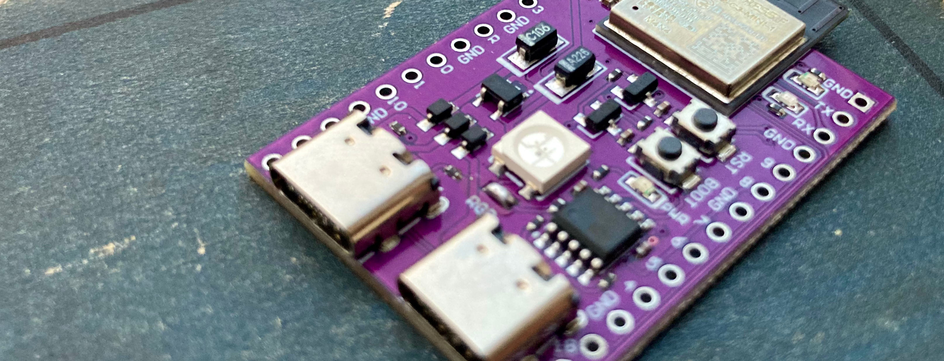
The (dev-) boards that I'm using the most are the ESP32 S2 Mini and ESP32 C3 Super Mini.
Typically they cost somewhere around 4-6€/each (but upwards of 10€ if you order from a shop in Germany). Ordering on eBay, the price per unit is lower when you order larger quantities, six boards should cost somewhere around 23€ in my experience.
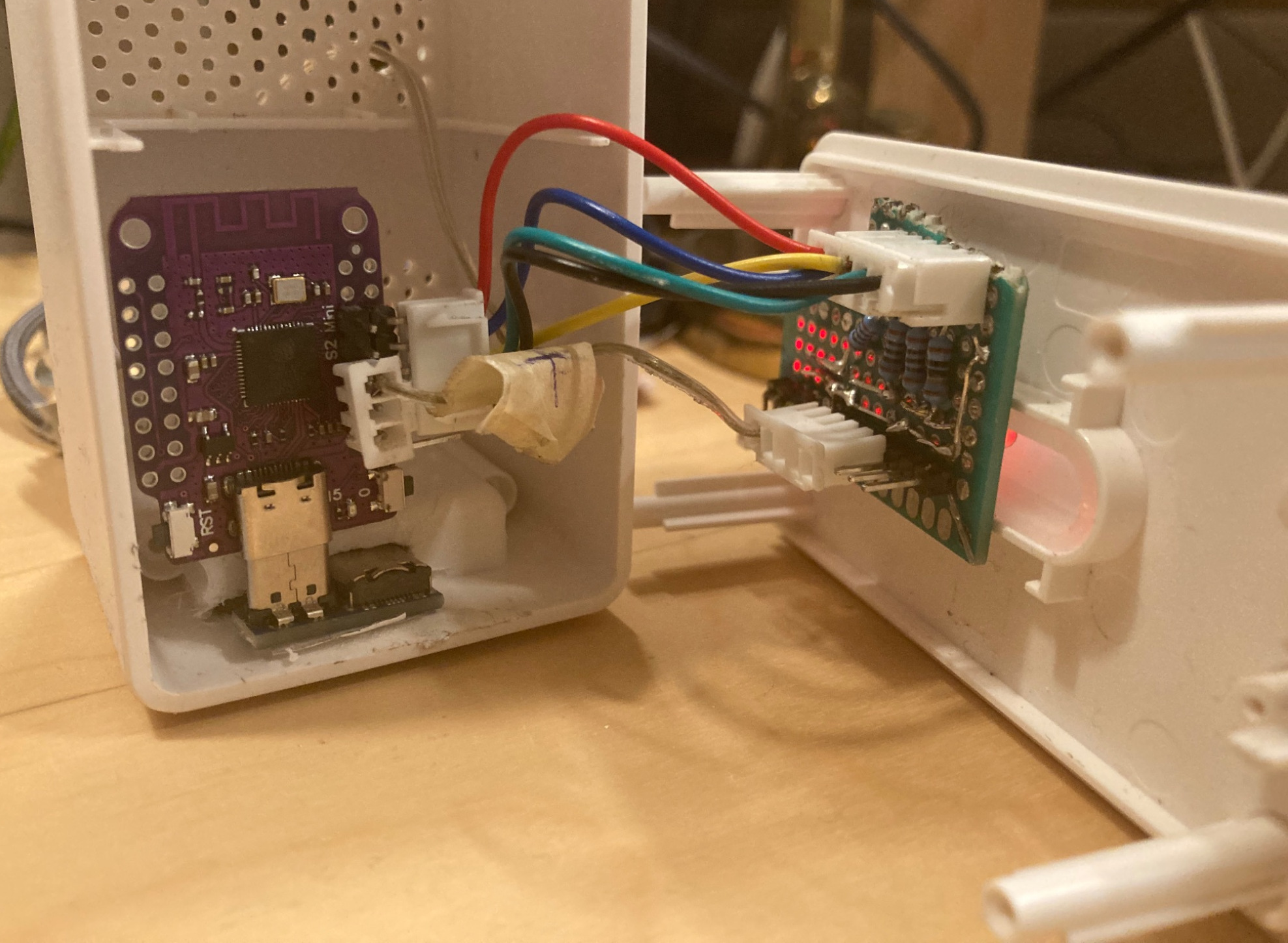
ESP32 S2 Mini used in my VINDRUTA project (inside of an IKEA VINDRIKTNING enclosure)
They are very flexible in terms of GPIO pins, and are capable of supporting any of their interfaces on any GPIO port. They are also small and have USB-C connectors.
For the boards that I have used, there is an ESPHome package under
packages/boards in my infra repo
with configs I use for each specific board. ESPHome uses/wraps PlatformIO and
therefore uses the same names and IDs2 for the chips, boards
and their variants that can be looked up in the PlatformIO board registry.
ESP32
Most (but not all) ESP323 have Bluetooth (most of those have BLE only), and is the successor of ESP82664. ESP32-S2 does not have Bluetooth.
Some ESP32-C3 series SoC are named ESP86855 (should not be confused with ESP8285, which are ESP8266).
The ESP32 chips support both the arduino and esp-idf frameworks6,
though esp-idf is generally preferred7.
- NodeMCU ESP32
- ESP32 WROOM
- ESP32 S2 Mini
- ESP32 S3 Pro
- ESP32 C3 Super Mini
- ESP32 C3 MINI-1
- ESP32 WT32-ETH01
- ESP32 WROVER
- QuinLED-ESP32
Some of these boards can be really weird, and I have in general run into more ESP32 boards with weird/unusual/hard-to-read silkscreen markings for the pins for example. Both the BLE and WiFi connections are remarkably stable on the boards I have used.
ESP8266
The ESP8266 chip only works with the arduino framework8, and
do not have a BLE chip. Later ESP8266 SoCs are named ESP8285 and ESP86845.
These are less powerful than the ESP32 boards, but are sometimes more reliable (getting I²C components to work in particular has been much easier in my experience). Interfaces (such as I²C, SPI, ADC) can only be used on their assigned pins, which can sometimes make it difficult to make a build fit together in a way that makes sense, though that is less of a concern if you can design your own circuit boards with KiCad or something similar.
In my experience, the WiFi connection on the ESP8266 boards is less stable than on the ESP32 variants that I have used.
Both the D1 Mini and NodeMCU boards are available with USB-C, and the D1 Mini in particular is a pleasant form factor.
Short note on frameworks
ESPHome supports the same frameworks as Platform.IO:
In short, ESPHome uses the arduino framework libraries as a middle layer in the stack, so using
the esp-idf framework cuts that out7. But for some boards, it can
be easier to use the arduino framework (for example using I²C on an ESP32 S2 Mini).
ESP8266 only support the arduino framework8.
References
ESP32 SoCs - Espressif: Lists all SoCs and their features and specifications.
ESP Product selector: Shows features for SoCs, or SoC with selected features.
esp-idf-notes - ve0x10.in Vedant Paranjape. See 7. ESP IDF in ESP IDF Lecture for a great overview and terminology.