Electronics
LEDs
The forward voltage drop of a LED depends on its color. The regular cheap 3-10 mm LED diodes range from (red, orange, yellow, etc) to (white, green, warm white, etc). They have a typical forward current of , and a maximum forward current of 1.
| Color | ||
|---|---|---|
| White | - | - |
| Warm White | - | - |
| Blue | - | - |
| Red | - | - |
| Green | - | - |
| Yellow | - | - |
| Orange | - | - |
| Pink | - | - |
| UV | - | - |
| Infrared (IR) | - |
The forward voltage drop of a diode (LED) can be measured with a multimter2. Turn the dial to the diode test mode, usually indicated with a diode symbol.
Resistance
Since these LEDs all generally have consistent forward currents and forward voltages, we can just use Ohms law and work out a reference table for common supply voltages.
| Supply voltage | |||
|---|---|---|---|
The resistor values are assume the typical forward current of .
| Forward voltage | |||
|---|---|---|---|
The voltage across the circuit is equal to the sum of the voltage across the components in the circuit, the resistor and the LED.
So for an LED with a forward voltage that is connected to a supply voltage , the voltage across the resistor is .
>>> I = 0.02     # 20 mA == 0.02 A
>>> Vs = 3.3
>>> Vf = 1.8
>>> V = Vs - Vf
>>> V/I          # R = V/I
75               # 75 Ohm
So to connect LED with a forward voltage of 1.8 V to 3.3 V, it should be protected by a 75 Ω resistor.
Pinouts
Regular and RGB 3mm and 5mm LED diodes3:
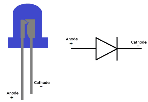
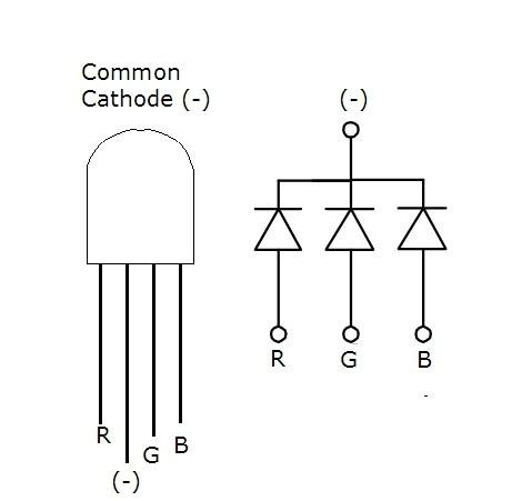
Single-color LED (left) and RGB LED (right) pinout.
- The cathode leg ( or ) is the shorter leg (usually ).
- The anode leg ( or ) is the longer leg (usually ).

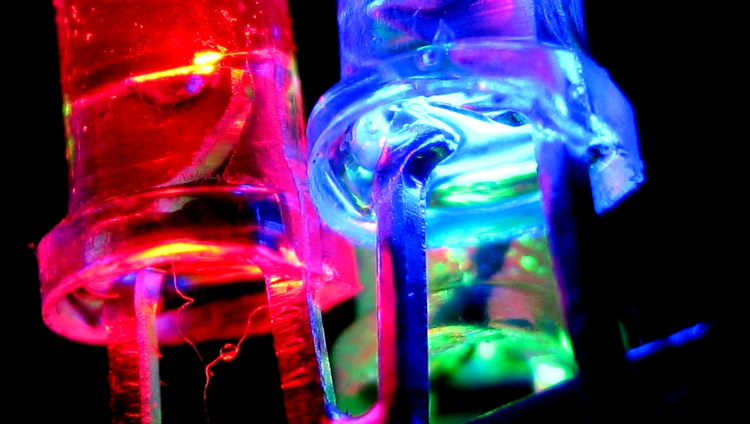
Anatomy of a green 5mm LED.
Wiring schematics
Multiple LEDs connected in series.
Proper way to connect multiple LEDs in parallel, each LED has its own current limiting resistor.
Stepping down voltage with resistence
There are multiple different ways to step DC Voltage down. Using a buck converter is simple, but they are bulky. But resistence reduces voltage (voltage falls as resistance increases).
To do that, you use two resistors and and "divide" the circuit between them4, connecting to and to . If and are of equal value, is reduced by half ().
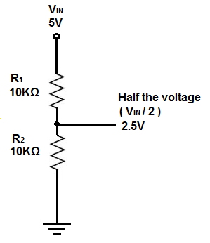
This circuit is called a voltage divider, is a pull-up resistor and is a pull-down resistor.
The general equation for reducting to :
Since both and are unknown (also we aren't in school, and experimentation is more interesting than algebra anyway) this involves some experimentation and picking some value resistor for and then calculating ca. what value resistor we need to get for .
For example is a reasonable starting point for . Stepping down to :
>>> v_out = 5
>>> v_in = 7
>>> r1 = 10
>>> (v_out*r1)/(v_in-v_out)    # 5*10 / (7-5)
25.0                           #   50 / 2
So to step down to using a pull-up resistor to , we need to use a pull-down resistor that is .
Potentiometers
| Potentiometer |
|---|
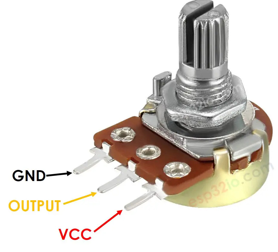 |
| Pinout of a regular potentiometer. |